Converting A Sonoff S31 To ESPHome
Purpose
I'm paranoid and never trust 3rd party firmware on my home automation equipment so I tend to only buy things I can put ESPHome on (or build them myself.)
This is an overview of how to convert the S31 to ESPHome. It touches more on the physical side of how to connect the wires and less on the compilation of the esphome firmware.
Requisite Disclaimer
You could probably hurt yourself and hurt the device. I'm not a professional. I'm entirely self taught on all of this. If you continue, you are copying the process of a mad man and that is probably a poor decision and that is totally on you.
If you do this and things go bad, I'd be glad to try to assist you in fixing it but I take absolutely no responsibility for your actions.
Go into this process assuming you've thrown your money away (with that said, I've yet to brick one of these). Also go into this process safely. Soldering irons are friggin' hot and can burn you. I know...
Preparation
Knowledge
- How the esphome works and the general usage of the commandline tool. I intend to get you to the point you can use the tool but this howto is so big I am not going to cover the tool usage itself aside from a super simple example.
- How to solder. If you don't know how to solder there are many videos on youtube to teach you. I really like this Branchus guy.
Necessary Tools
- You will need a way to solder. I'm in love with my Pinecil but any soldering iron will do.
- A Phillips screw driver.
- Something thin and flat to pop off a piece of plastic. A knife would work. I used a spudger.
- A computer. I'm pretty sure this can be done in Windows but my only experience is from a Linux interface so that is what this is going to cover.
- A USB to TTL Serial Adapter. That is just an example, it doesn't need to be that one.
- Some small wire AWG22-AWG24 works well. Different colors is nice but not necessary.
Optional Tools
- Some IC Test Hook Clips. Again, those are just a suggestion but you may find a better deal elsewhere.
- A Small Breadboard and a Variety of Dupont Jumper Wires
The Disassembly
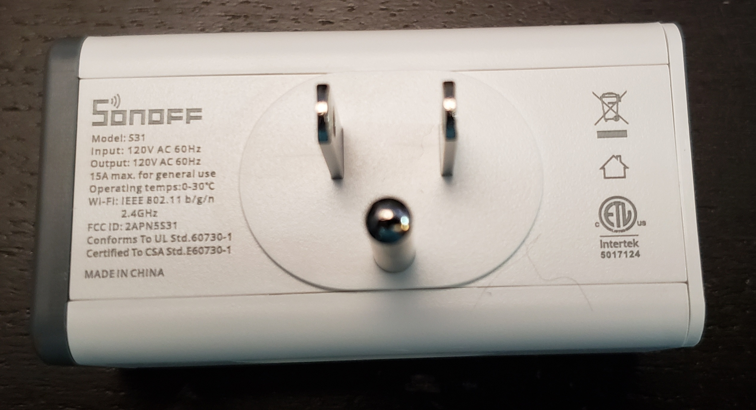
So you have your Sonoff S31 sitting in front of you like so:
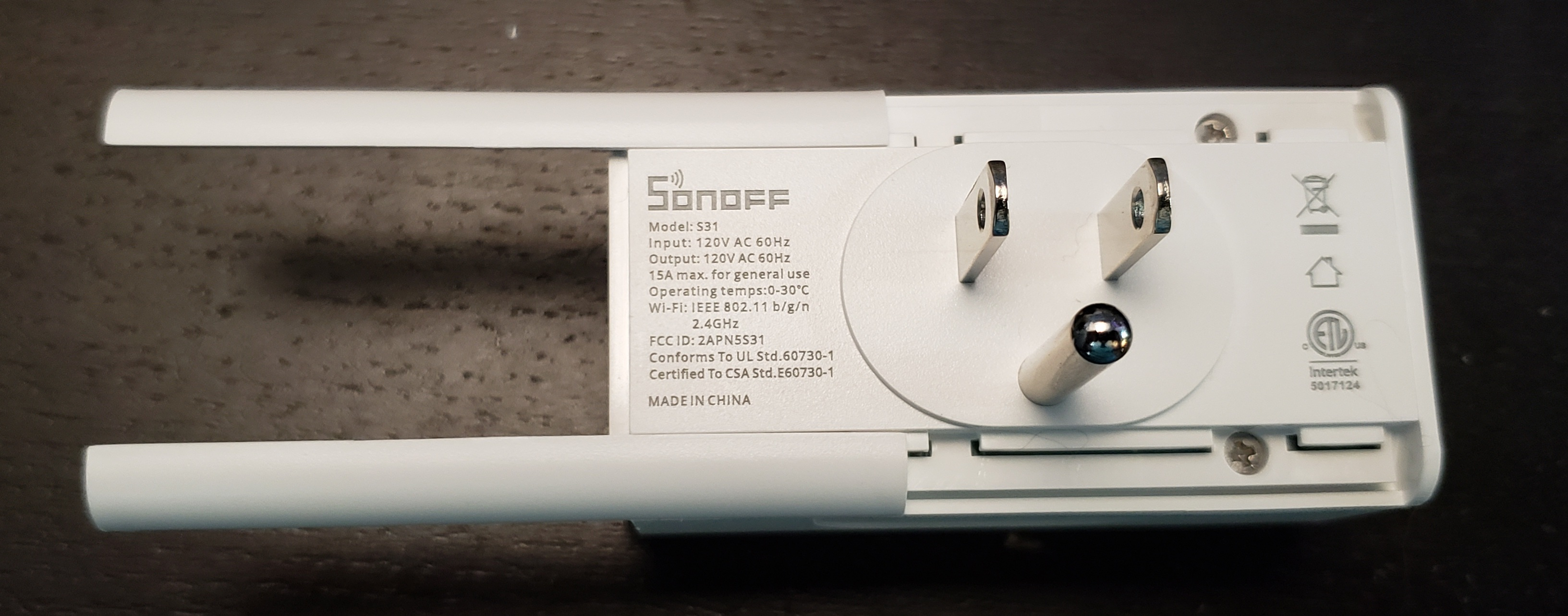
First, you need to pop off the dark grey piece with the power button. If you are OCD, be careful not to scratch or mar anything. It should pop off quite easily.

Next the two rounded corners slide off.

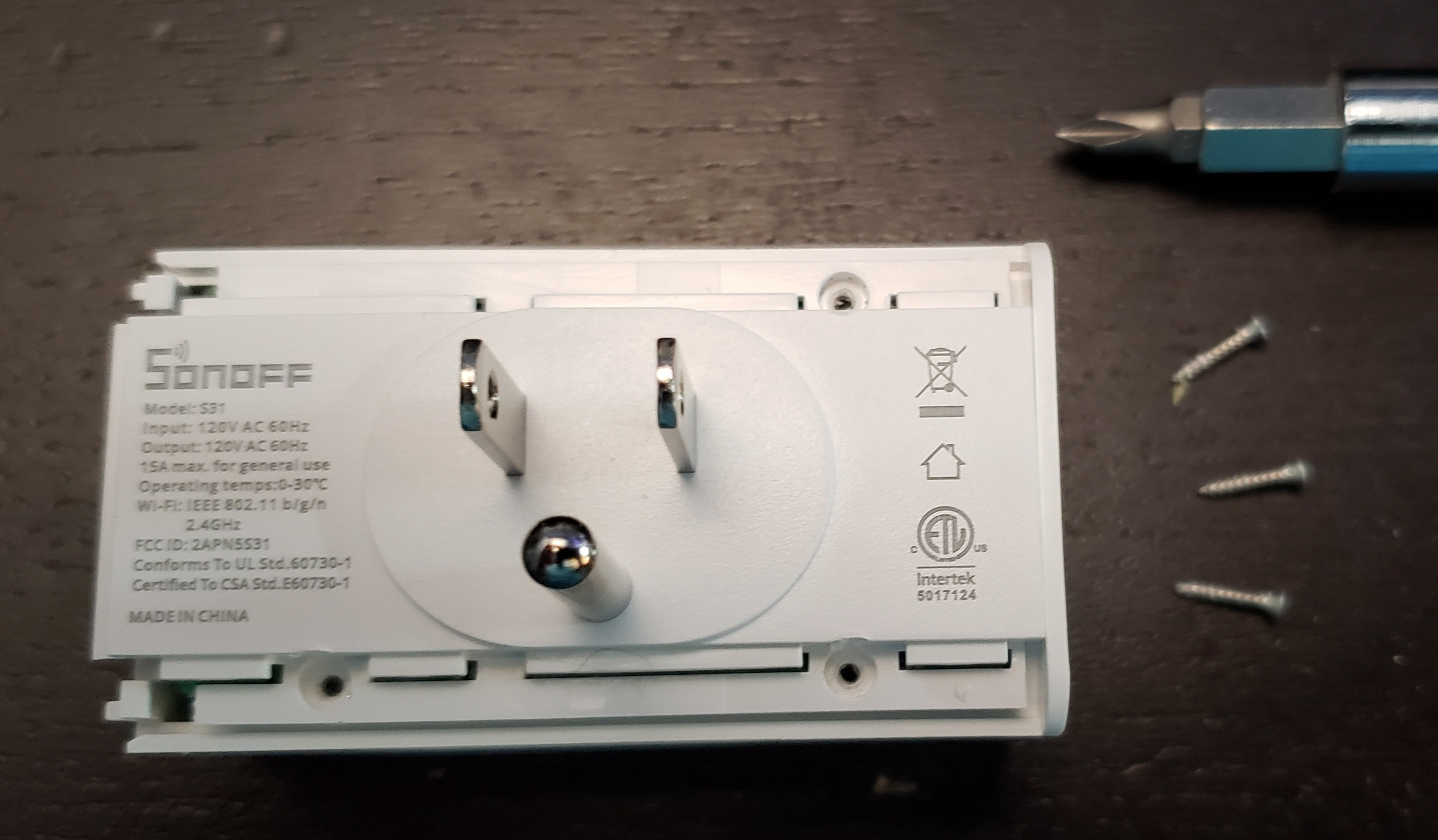
Next, there are 3 small screws to remove
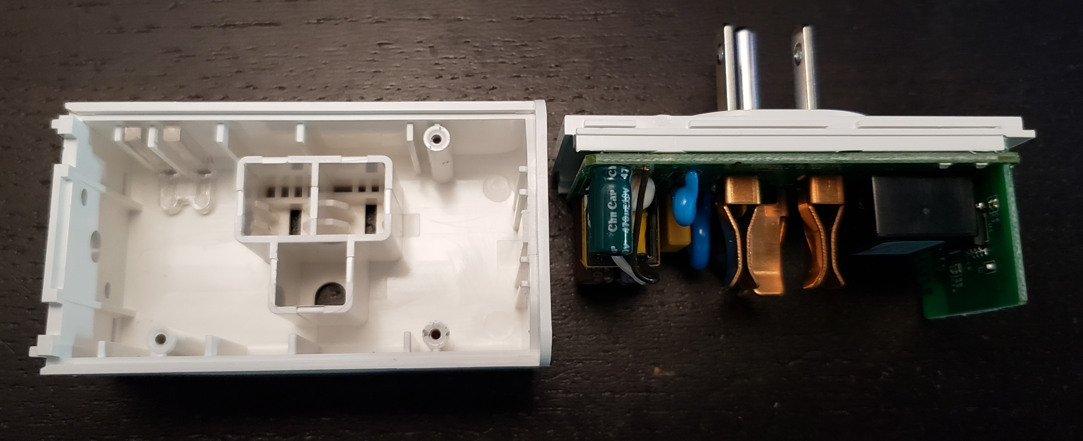
Finally, you can now pull the front and back apart.
Store all of the loose pieces somewhere safe so you can reassemble it later.
Preparing To Flash
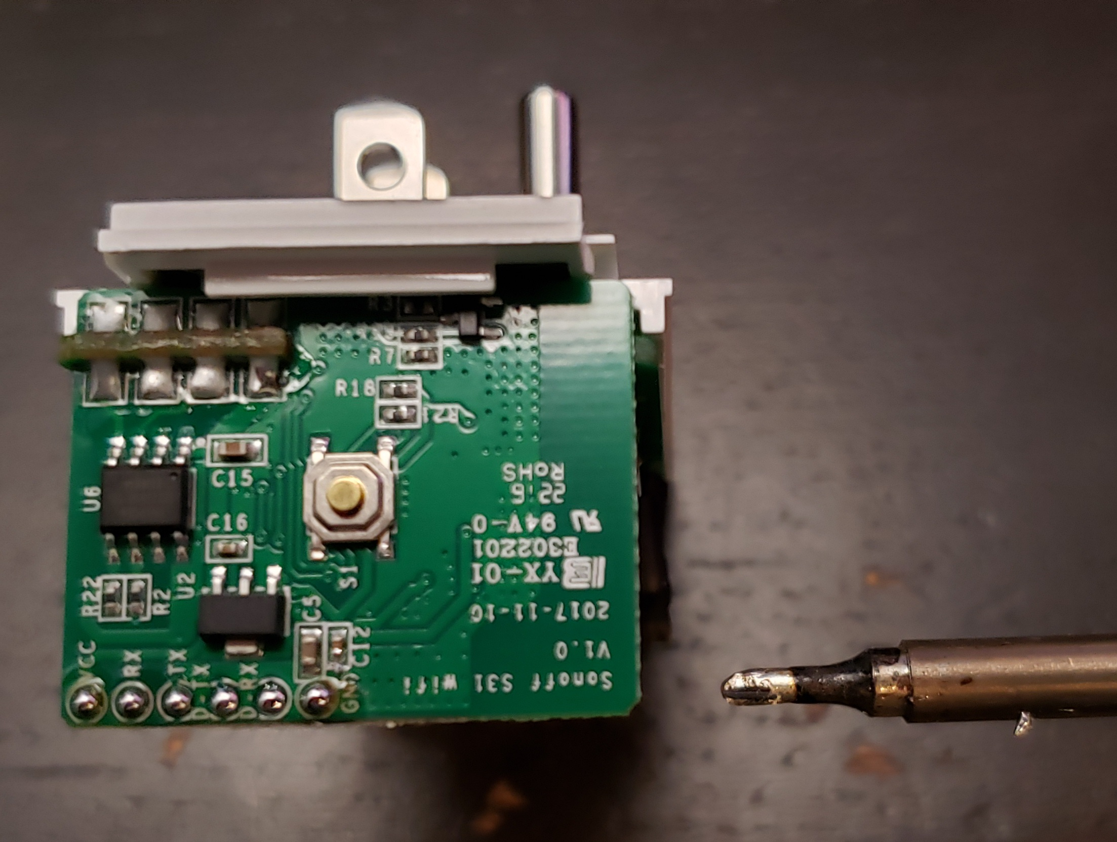
Now you have your device that looks like this.

The first thing I recommend is to use your soldering iron to tin the pads that you see in the bottom left corner. I prefer to have a nice ball of solder. It makes attaching wires much easier.
Technically you only really need to tin the VCC, TX, RX and GND pads. I did them all because I'm a bit OCD.
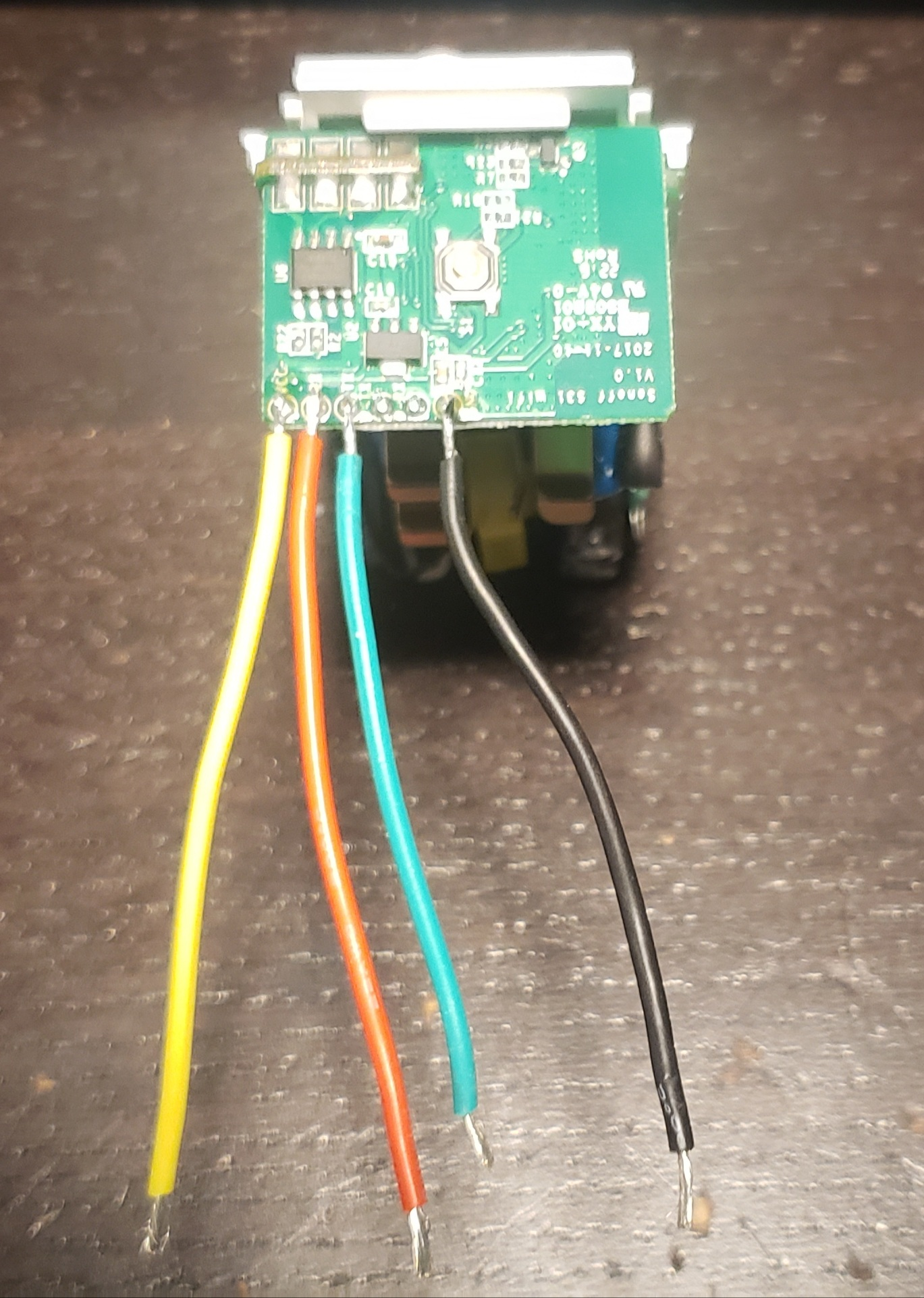
Now take some wires with a pre-tinned end and attach them to the VCC, TX, RX and GND pads. I chose the following colors.
VCC = Yellow (incoming voltage)
TX  = Green (transmit)
RX  = Red (receive)
GND = Black (ground)
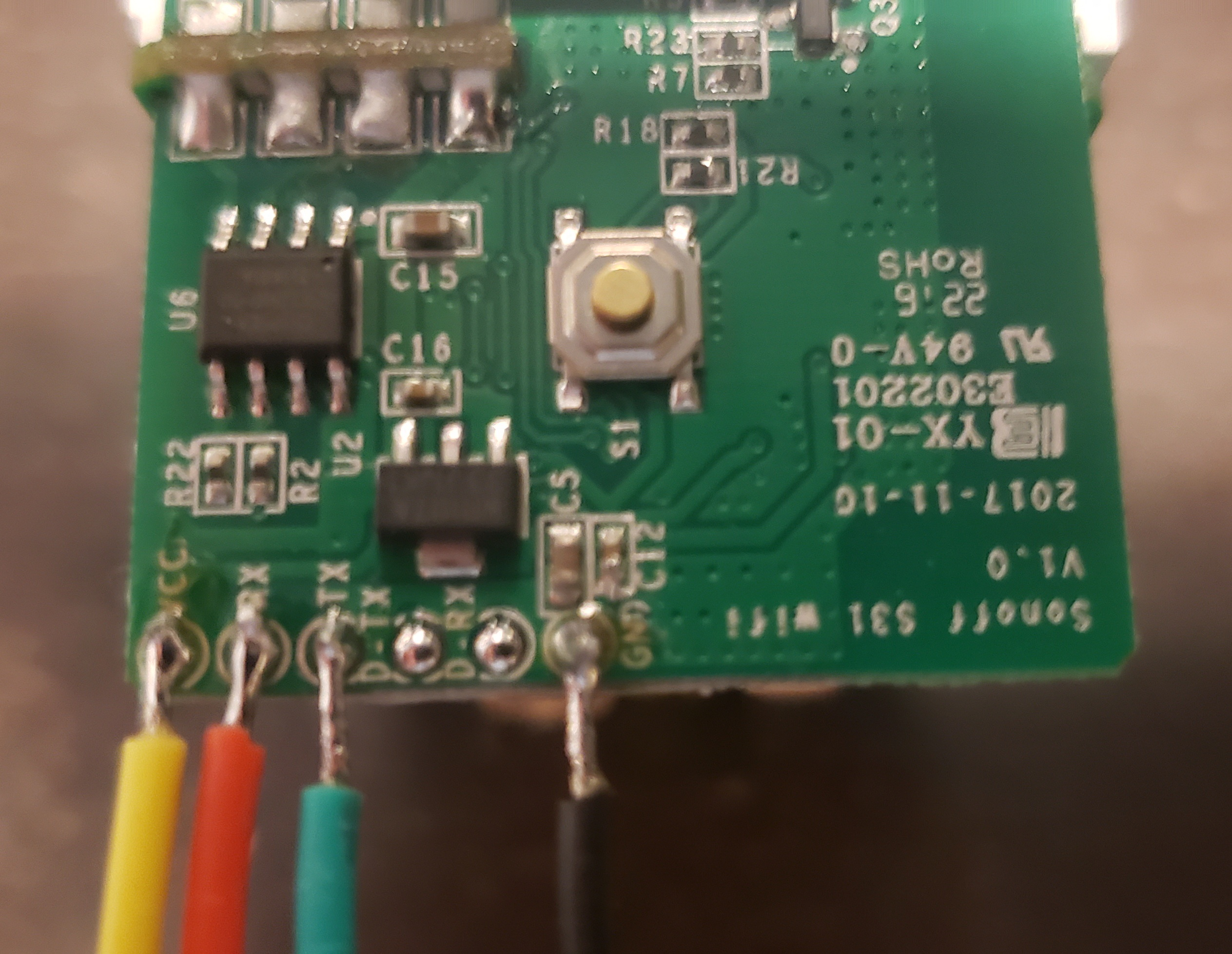
So, if you are doing this the way I'm doing it, you should have a device that looks like this.
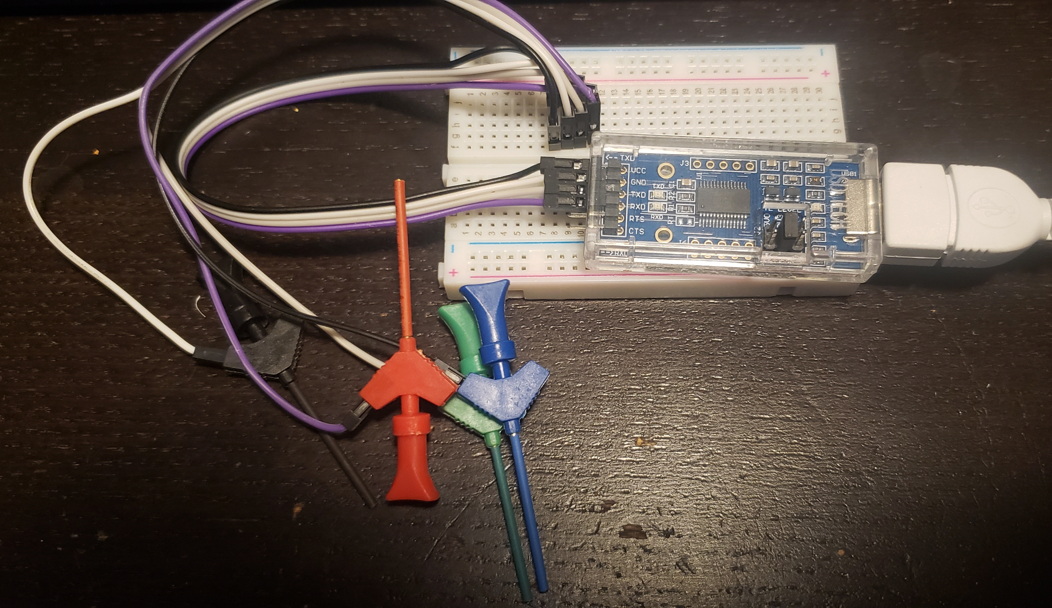
My setup is somewhat overkill. Ignoring the breadboard and just focusing on the USB device, here are the most important bits:
- SUPER IMPORTANT!!! It needs to be set to 3v3. If it is set to 5v5 you may damage the device.
- I have wires hooked up to VCC, GND, TXD and RXD.
Now I didn't have a yellow clip so I used Blue for VCC, otherwise I kept the coloring the same.
VCC = Blue (outgoing voltage)
GND = Black (ground)
TX  = Green (transmit)
RX  = Red (receive)
Connect the wires from your USB device to the pigtail wires you soldered onto your Sonoff S31. Super important to note... We criss cross the TX/RX wires so that one side's TX connects to the other side's RX and vice versa.
If you think about TX as talking and RX as listening, it would make no sense to hook up TX to TX because then it would end up being like US politics where each party is talking but no one is listening. So instead we want one side talk, and the other to listen.
Just to help here is a wiring diagram.
SONOFF S31 <--> USB Programmer
       VCC <--> VCC
       GND <--> GND
       TX  <--> RX
       RX  <--> TX
And you should end up with something like this.

Putting ESPHome On Your Sonoff S31
Now that you have your USB programmer hooked up directly to the device, all we have to do is the computer side of it.
Get the ESPHome YAML file. You can currently find that here but in case that goes away at some point I'm also going to include a copy here.
You will need the esphome cli app installed and ready to go.
The Flash Process
-
Unplug the USB device.
-
Make sure the esphome yaml file is altered appropriately.
-
Have the command line ready to run. It should look something like this:
esphome run --device /dev/ttyUSB0 whatever_you_called_your_file.yaml -
Press and hold the power button on the Sonoff S31. (You can do it directly on the board. You won't get shocked or anything.)
-
While holding the power button, plug in the usb device. This puts the Sonoff S31 into flash mode.
-
Release power button.
-
Run the esphome command you prepared. With any luck you will see it go through the process of compiling the firmware and then writing it to the device.
Troubleshooting
- If you had a problem with the esphome command itself, check google. Other people have probably had the same problem and they will have a fix.
- If it just won't seem to work, double check your wiring. Make sure you criss crossed your TX/RX wires. Make sure everything is firmly connected.
- Try the process again a few times. It can be a bit wonky and timing can be a factor.
- Good news is, if it never got to the 'writing' part of the process your device was probably never altered and it shouldn't be bricked.
Finishing Up
- Use your soldering iron to remove the 4 wires you connected. When you are done it should look like this again.
- Then you just complete the disassembly process in reverse.